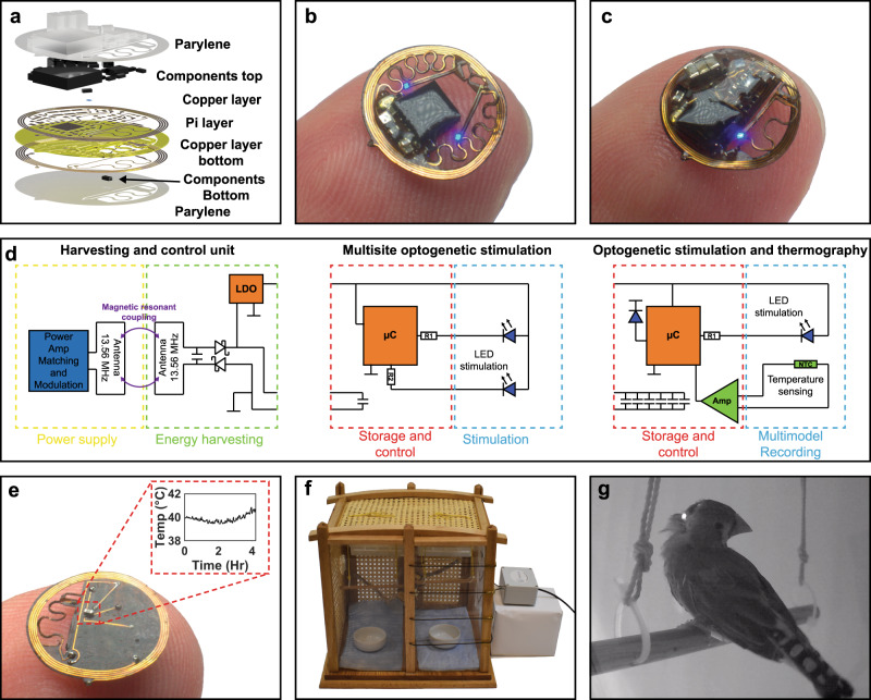
Fig. 1. Device overview and basic operating principles.
a Exploded-view layout of the constituent layers of the system. b Photographic image of the dual optogenetic stimulation probe device balanced on a finger. c Photographic image of the multimodal optogenetic stimulator and thermography device balanced on a finger. d Schematic diagram of electrical operating principles of the two devices with harvesting and control unit (left), dual optogenetic probe stimulation circuit diagram (middle), and multimodal optogenetic stimulation and thermography circuit diagram (right). e Photographic image of the back of the multimodal optogenetic stimulator and thermography device with inset showing temperature sensing capabilities over a 4-hour period. f Photographic image of the experimental arena with stimulation arena in the right chamber. g Photographic image of finch perched in the experimental arena with IR LED activated during data uplink event.

