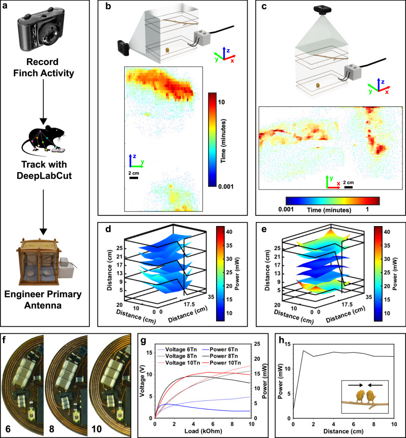
Fig. 2. Behavior guided primary antenna design and secondary antenna optimization.
a Workflow diagram showing behavior guided antenna design for resonant magnetic coupling-based devices. b Rendered schematic of side camera recording setup (top) and heat map indicating spatial location of the finch. c Rendering of cage with top camera (top) and heat map indicating spatial location. d Spatial mapping of power distribution for the subdermally implantable device in an arena with dimensions 20 cm x 35 cm x 35 cm with 4 turn antenna equidistantly spaced and 10 W RF input power. e Spatial mapping of power distribution for the subdermally implantable device in an arena with dimensions 20 cm × 35 cm × 35 cm with 4 turn antenna spaced in a Helmholtz-like configuration with 10 W RF input power. f Photographic image of secondary antenna with 6, 8, and 10 turn configurations. g Power vs. load curve for the miniatured device at the center of the arena 25 cm from the floor measured with primary antenna in Helmholtz-like configuration and an input power of 10 W. h Available device power vs. distance between two wireless devices at the center of the arena 25 cm from the floor with wires in a Helmholtz-like configuration and an input power of 10 W.

