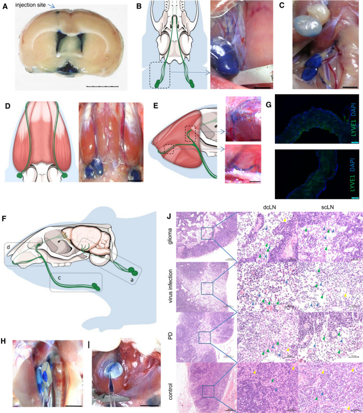
Figure 1.

Anatomical structures of rat BLF drainage routes to cervical lymph nodes. A, Evans blue was injected into the lateral ventricle to optimize the visualization of BLF drainage.(n = 3) Bar: 5 mm. B, 30 min after, 10 μL of 10% Evans blue was injected into the lateral ventricle, dcLNs and their afferent vessels were dyed blue, whereas scLNs and their vessels remained gray or slightly blue C. (n = 5) Bars: 2 mm. D, 30 min after injection of 20 μL Evans blue, scLNs and their afferent vessels became dark blue after dcLNs. (n = 5) Bar: 5 mm. E, A portion of scLN afferent vessels crossed through the infraorbital foramen, while the others exited via the nasal cavities. Bars: 2 mm. F, Schematic diagram of rat BLF drainage routes from the cranium to cervical lymph nodes. G, Immunofluorescence of dcLN‐ and scLN‐related afferent vessels for LYVE‐1. Bars: 100 μm. H, Collection of BLF from dcLN afferent vessels. Bar: 5 mm. I, Collection of BLF from scLN afferent vessels. Bar: 5 mm. J, Both dcLNs and scLNs connected to brain lymphatic vessels appeared to have pathological changes in brain glioma, virus infection and PD models, including the expansion of the subcapsular sinus, increasing of macrophages and lymphocytes, decreasing of desmocytes in the subcapsular sinus. Green arrowheads: macrophages, blue arrowheads: lymphocytes, yellow arrowheads: desmocytes Bars: 200 μm and 50 μm.
