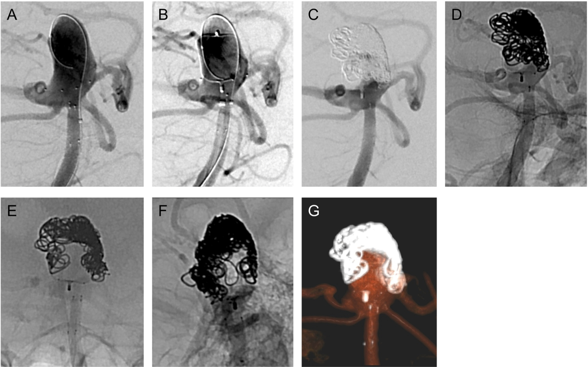
Fig. 3.

(A) Vertebral arteriogram in same projection as Fig. 2D–E shows the coiling catheter looped at the dome of the aneurysm lumen and the PulseRider deployed in the distal basilar artery. (B) Vertebral arteriogram in same projection after deploying and detaching WEB atop the PulseRider. The left aneurysm base is not covered by the WEB, and contrast reaches the aneurysm lumen’s dome after passing through the left aneurysm neck. (C) Vertebral arteriogram in same projection after placing multiple platinum and gel coils. The coils were placed atop the WEB and at the left aneurysm base. The aneurysm lumen’s dome is protected. (D) Unsubtracted fluoroscopic image (in same projection as Fig. 3C) demonstrating position of coils. (E) Unsubtracted fluoroscopic image (in same projection as Fig. 2A) showing coils atop the WEB atop the PulseRider. (F) Unsubtracted fluoroscopic image (in same projection as Fig. 2B) showing the same. (G) Volume-rendered reformat of dual-volume flat panel CTA showing the WEB, PulseRider, and coil construct.
