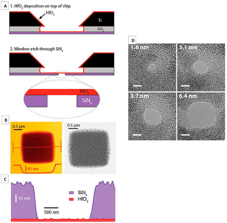
FIG. 6:
Freestanding HfO2 membrane fabrication: (a) 1–Atomic layer deposition is used to deposit a 3–8 nm thick HfO2 layer onto the trench side of a freestanding silicon nitride window, and 2–Reactive ion etching of a predefined window to expose the freestanding HfO2. (b) Atomic force microscopy (AFM) topography (left) and dark-field scanning transmission electron micrograph (right) of a freestanding HfO2 region. (c) Energy dispersive spectroscopy (EDS)-based thickness map of SiNx and HfO2 (thickness estimated from AFM) and (d) bright-field TEM images of nanopores of diameters 1.6–6.4 nm, drilled in a HfO2 membrane. (Reprinted with permission from ACS publications. Copyright 2007.7)

