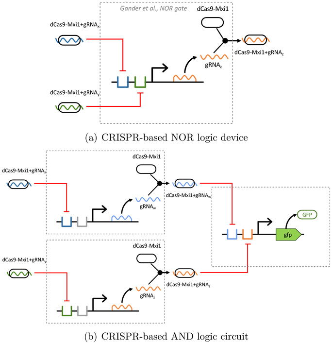
Figure 4:
CRISPR/Cas9-based devices and circuits drawn using SBOL Visual 2. (a) NOR device from Gander et al.,22 in which gRNA/dCas9 complexes repress operators upstream of a promoter that regulates the production of gRNA, which in turn binds with dCas9-Mxi1 to complete implementation of a digital NOR logic device. Note the use of color coding to distinguish the x/y/z gRNAs, and the dashed module boundary identifying device inputs and outputs. (b) Interconnection of three NOR devices to implement an AND circuit from Gander et al.22 Expression of green fluorescence protein (GFP) is used as output and module boundary crossings show how devices are interconnected to form a circuit.

