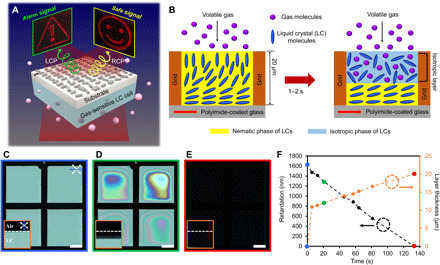
Fig. 1. Design of gas-responsive liquid crystal (LC) cells and their optical responses.

(A) Schematic of the proposed holographic metasurface gas sensor platform. A holographic metasurface integrated with gas-responsive LCs projects a safety signal (smiley face) in the absence of a target dangerous gas, while an alarm signal (exclamation mark) is displayed upon the detection of the gas. Right circularly polarized (RCP; yellow arrow) illumination creates a “safe signal,” and left circularly polarized (LCP; green arrow) illumination produces an “alarm signal.” (B) Schematic illustration (side view) of gas-responsive LCs that are hosted in a microwell. Initially, the LC cell has a hybrid anchoring configuration because of the vertical orientation of the LCs at the air interface and the unidirectional tangential orientation set by the rubbed polyimide coated onto a glass substrate. When volatile gases are introduced, however, the LC ordering is lowered because the isotropic gas molecules partition into the LC layer. Consequently, the nematic-to-isotropic phase transition occurs from the air interface and the isotropic layer expands as more gas molecules are diffused into the LCs. (C to E) Sequential optical micrographs (top) of the LC cell upon the exposure of IPA gas; see movie S1. Scale bar, 100 μm. The insets in (C) to (E) show the corresponding side view micrographs. The LC cell is placed in a closed chamber with a concentration of IPA gas of around 200 ppm. White arrows represent the polarization of the polarizer (input) and analyzer (output). Blue arrows represent the rubbing direction. (F) Measured retardation and calculated isotropic layer thickness over time. Data corresponding to (C) to (E) are marked by the blue, green, and red dots.
