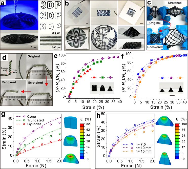
Fig. 4. Fabricating 3D TCHs with the extruding printing technique.
a Digital images of printed spiral TCHs via a typical extrusion 3D-printing technique (nozzle size: 22 G, moving rate: 5 mm s−1). b Digital images of different TCH patterns and 3D structures on polyethylene terephthalate, indium-tin-oxide-coated glass, paper, and cotton fabric substrates. c Omnidirectionally stretching a TCH mesh. The mesh was first made by extrusion 3D-printing technique with five layers on a PET substrate. Then, it was carefully peeled from the substrate, stretched, and released to its original states. d Making free-standing helical TCHs using co-axial 3D-printing technique with a stiff polymer. e, f Resistance changes of TCHs under different strains with different geometry shapes. g, h Finite element simulation of force distribution and strains in corresponding TCHs in (e) and (f). Dash lines and dots are simulated, and experimental results of compressing TCHs under different external forces applied, respectively. Inset images show the strain distributions of TCHs with the external forces applied of 0.5 and 1 N, respectively. Scale bars in (b), (c), (e), and (f) are 1 cm.

