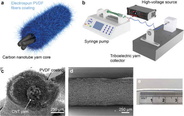
Figure 1.
Fabrication and characterization of the triboelectric yarn. (a) Schematic of the triboelectric yarn core–shell structure. (b) Schematic of the fabrication setup for the triboelectric yarn. The setup is based on an electrospinning machine with a custom-made rotating collector. (c, d) SEM images across the cross section and along the length of the triboelectric yarn. (e) Photograph of the triboelectric yarn.

