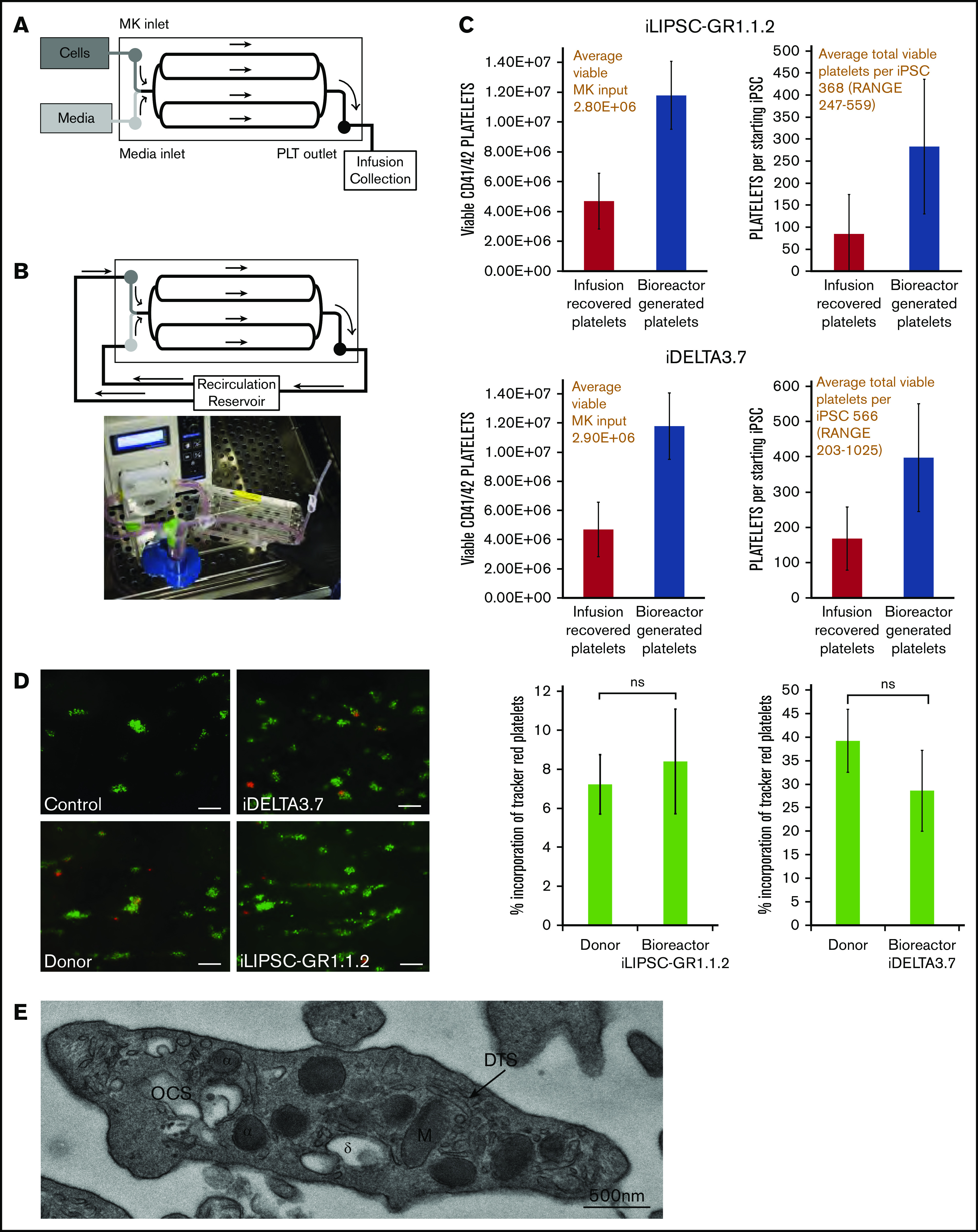
Figure 5.

In vitro platelet production using a bioreactor. (A) Schematic of a bioreactor (Platelet BioGenesis) set up during the MK-seeding step. (B) Schematic of the bioreactor set up during the recirculation (PLP production) step, and photograph of setup. (C) Bar graphs for n = 3 runs of the bioreactor for iLIPSC-GR1.1.2 (top) and iDELTA-3.7 n = 3 runs (below) showing the final viable platelet output (left). The number of viable MKs input are shown in red above and the number of viable platelets produced per starting iPSC (right) with the total per iPSC in red above. Red bars are infusion recovered platelets and blue bars bioreactor generated. (D) In vitro thrombus formation under flow. Left panel: representative images from control, donor blood, iDELTA-3.7, and iLIPSC-GR1.1.2 bioreactor-generated platelets. In vitro–derived or donor platelets (red) human donor platelets (green). Scale bars, 20 μm. Right panel: the percentage incorporation of Cell Tracker Red–stained platelets for n = 3 replicates (3 × 80 images per chip scored) for iLIPSC-GR1.1.2 (left) and iDELTA-3.7 (right). For both lines, the incorporation of donor platelets and bioreactor platelets in thrombi are not significantly different from each other. (E) Transmission electron microscopy of a bioreactor-generated platelet. Cross-section of a bioreactor-generated platelet from LIPSC-GR1.1 containing both α (α) and δ (δ) granules, open canicular system (OCS), dense tubular system (DTS), and mitochondria (M). Scale bar, 500 nm; original magnification ×5000.
