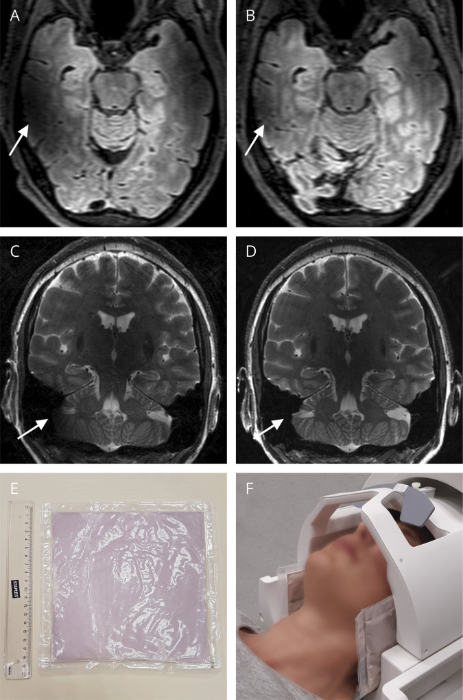
Figure 1. Use of Dielectric Pads.
Illustration of the effect of dielectric pads on (A and B) 3D fluid-attenuated inversion recovery (FLAIR, 0.7 mm isotropic resolution) and (C and D) T2-weighted sequences (0.3 × 0.3 × 1.5 mm resolution). In (A and C), no pads are used, whereas in (B and D) they are. Arrows indicate corresponding areas before and after signal improvement (A versus B, C versus D). The dielectric pads used in this case are 19 × 19 cm (E); pad placement for obtaining images (B and D) is demonstrated in image (F). Of note, optimal pad placement depends on the head size and shape.

