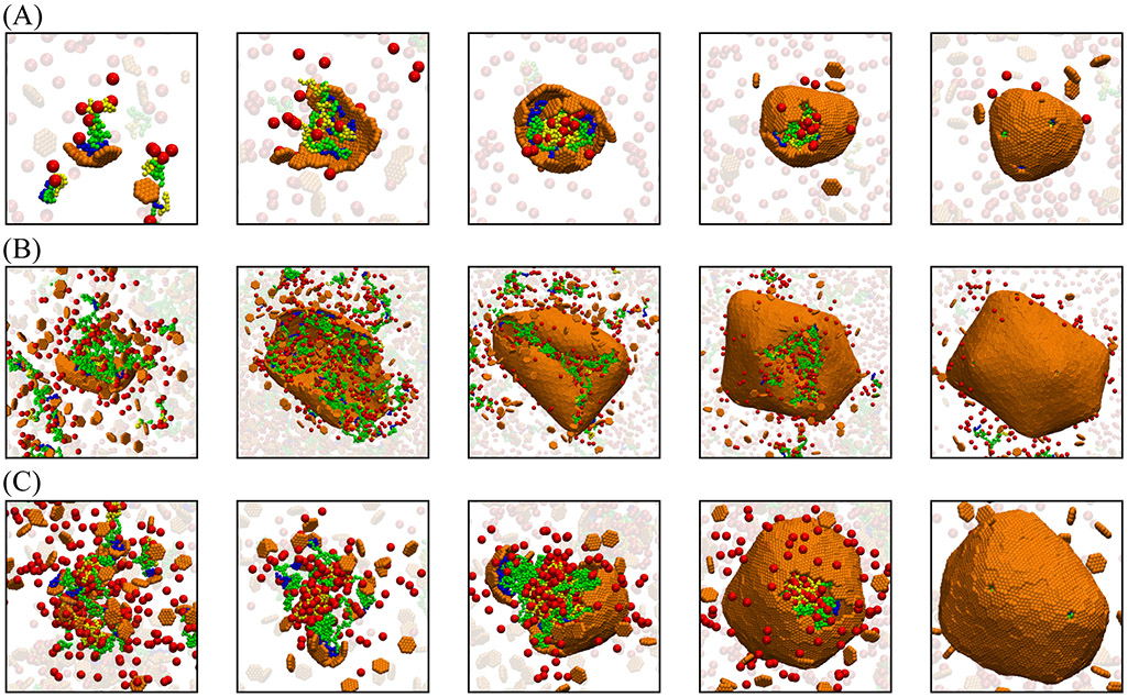
Figure 2:
Snapshots from simulation trajectories illustrating typical assembly pathways and products (Animations corresponding to these trajectories are provided in the SI, videos S8). (A) One-step assembly pathway leading to full shells: Coalescence of the cargo and scaffold occurs concomitantly with shell assembly. The mean size of assembled shells (defined as the radius of gyration of shell subunits) is R = 6.3 ± 0.5. Parameter values are: shell spontaneous curvature radius R0 = 8.0, scaffold contour length Ls = 24 (Lsm = 10, Lsc = 7), and subunit-subunit interaction strength εhh = 2.85 (all lengths and energies are given in units of r* and kBT respectively). (B) One-step assembly with sparse cargo loading, with mean shell size R = 18 ± 3.6, for R0 = 22, Ls = 64 (Lsm = 50, Lsc = 7 ), and εhh = 2.65. (C) Two-step assembly pathway: The scaffold and cargo phase separate prior to shell assembly, due to increased valence of the scaffold-cargo binding domain fsc = 0.42. The shell size is R = 10.66 ± 0.60. Parameter values are: R0 = 22, Ls = 64 (Lsm = 30, Lsc = 27), and εhh = 2.65. For (A)-(C), the scaffold-shell and scaffold-cargo interaction strengths are εsh = 2.5 and εsc = 1.0. Snapshots are shown at different scales for clarity.

