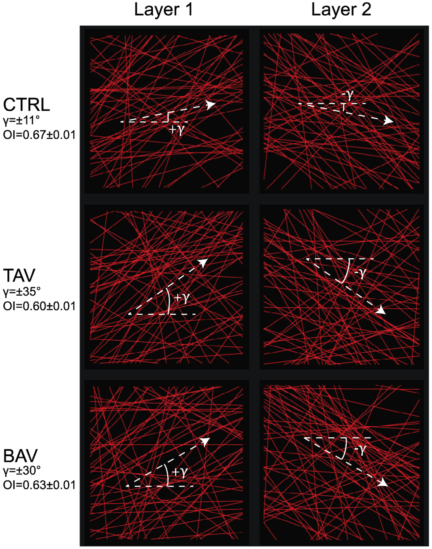
Fig. 2.

Collagen fiber networks for the CTRL, TAV, and BAV tissues shown on CIRC-LONG plane. Collagen fibers are denoted by red straight lines. Panels in left column represents the fiber network in layer 1 of the computational model, while panels in right column shows the networks in layer 2. Crimp of the fibers were not represented explicitly in our model, but were taken through the recruitment stretch in the fiber constitutive model. Dashed lines show the mean fiber direction for each network.
