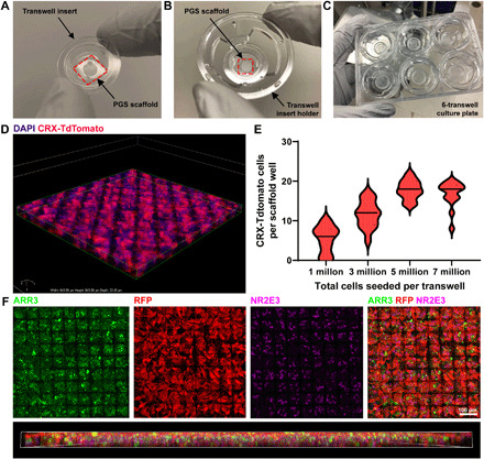
Fig. 5. Generation of PGS ice cube tray PR scaffold constructs.

(A to C) Low-magnification photographic images depicting scaffold mounting into the transwell insert. (A) Transwell insert with PGS scaffold below. The outer edge of the scaffold was glued to the transwell insert with soft PDMS. The area of the transwell insert removed to mount scaffolds was 19.6 mm2 (internal diameter, 5 mm). (B) Transwell insert holder with a PGS ice cube tray scaffold mounted into a transwell insert. (C) Six-transwell scaffold cell culture system. (D to F) Laminin-coated ice cube tray scaffolds are readily filled with hPSC-derived CRX+/tdTomato-expressing PRs. (D) 3D rendering of a scaffold (176 μm by 185 μm by 22 μm) confirms successful capture of multiple PRs (labeled in red) in individual capture wells. Cell nuclei are labeled with 4′,6-diamidino-2-phenylindole (DAPI) (blue). (E) Cells were seeded onto scaffolds at varying densities to determine the minimum number required to achieve the maximum carrying capacity of CRX+/tdTomato-PRs per well. Median (bold dashes) and quartiles (fine dashes) are shown within individual violin plots. (F) Scaffolds seeded with CRX+/tdTomato-PRs (RFP+, red) contain both ARR3-expressing cone PRs (green) and NR2E3-expressing rod PRs (pink). A 3D lateral view of the scaffold demonstrates relatively even distribution of ARR3+ cones and NR2E3+ rods. 3D rendering is 644 μm by 644 μm by 20 μm. Photo Credit: In-Kyu Lee, Department of Electrical and Computer Engineering, University of Wisconsin–Madison.
