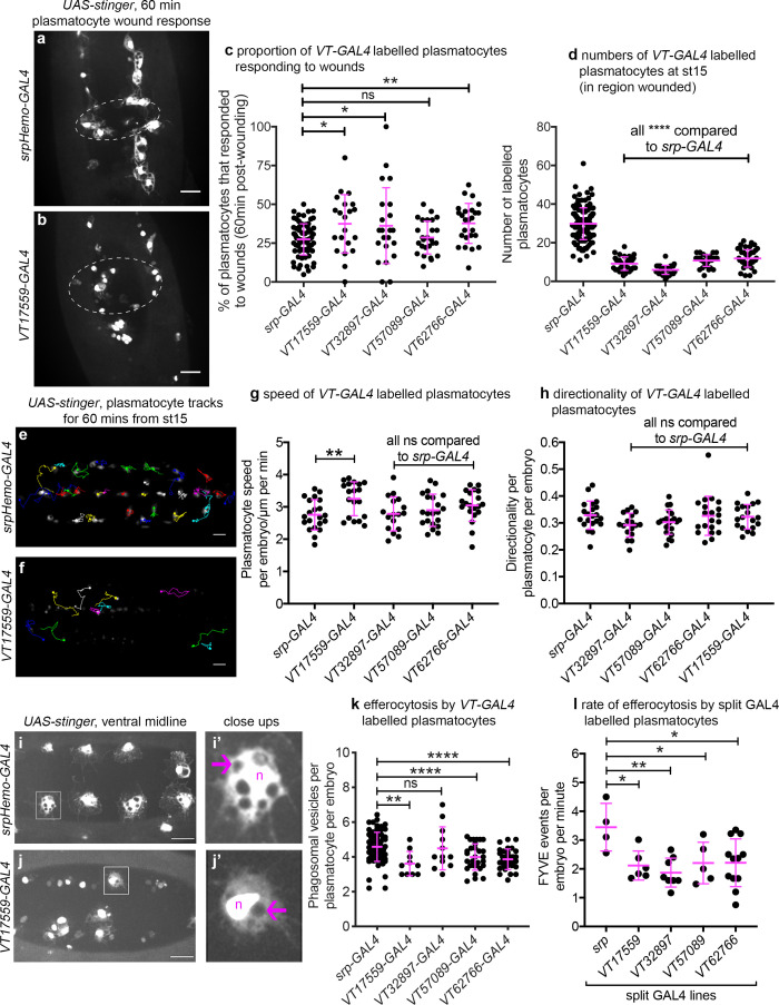
Figure 8. Drosophila plasmatocyte subpopulations demonstrate functional differences compared to the overall plasmatocyte population.
(a–b) Example images showing plasmatocyte wound responses at 60 min post-wounding (maximum projections of 15 μm deep regions). Cells labelled via UAS-stinger using srpHemo-GAL4 (a) and VT17559-GAL4 (b); dotted lines show wound edges. (c–d) Scatterplots showing percentage of srpHemo-GAL4 (control) or VT-GAL4-labelled plasmatocytes responding to wounds at 60 min (c) or total numbers of labelled plasmatocytes in wounded region (d); p=0.018, 0.041, 0.99, 0.0075 compared to srpHemo-GAL4 (n = 77, 21, 22, 26, 25) (c); p<0.0001 compared to srpHemo-GAL4 for all lines (n = 139, 35, 37, 30, 44) (d). (e–f) Example tracks of plasmatocytes labelled with GFP via srpHemo-GAL4 (e) and VT17559-GAL4 (f) during random migration on the ventral side of the embryo for 1 hr at stage 15. (g–h) Scatterplots showing speed per plasmatocyte, per embryo (g) and directionality (h) at stage 15 in embryos containing cells labelled via srpHemo-GAL4 (control) or the VT-GAL4 lines indicated; p=0.0097, 0.999, 0.82, 0.226 compared to srpHemo-GAL4 (n = 21, 19, 17, 21, 20) (g); p=0.998, 0.216, 0.480, 0.999 compared to srpHemo-GAL4 (n = 21, 19, 17, 21, 20) (h). (i–j) Example images of cells on the ventral midline at stage 15 with labelling via UAS-stinger expression using srpHemo-GAL4 (i) and VT17559-GAL4 (j); plasmatocytes shown in close-up images (i’, j’) are indicated by white boxes in main panels; arrows show phagosomal vesicles, ‘n’ marks nucleus; n.b. panels contrast enhanced independently to show plasmatocyte morphology. (k) Scatterplot showing phagosomal vesicles per plasmatocyte, per embryo at stage 15 (measure of efferocytosis/apoptotic cell clearance); cells labelled via srpHemo-GAL4 (control) or the VT-GAL4 lines indicated; p=0.0020, 0.99, 0.0040, 0.0002 compared to srpHemo-GAL4 (n = 76, 10, 12, 29, 31). (l) Scatterplot showing number of times 2x-FYVE-EGFP sensor recruited to phagosomes (FYVE events) per plasmatocyte, per embryo in plasmatocytes labelled via the split GAL4 system; p=0.019, 0.0034, 0.039 and 0.015 compared to srp control (n = 4, 6, 8, 5 and 12 embryos). Lines and error bars represent mean and standard deviation, respectively (all scatterplots); one-way ANOVA with a Dunnett’s multiple comparison test used to compare VT lines with srp controls in all datasets; ns, *, **, and **** denote not significant (p>0.05), p<0.05, p<0.01, and p<0.0001, respectively. All scale bars represent 20 μm. See Supplementary file 1 for full list of genotypes. N.b. Figure 8—figure supplements 1–3 show analysis of subpopulation cell morphology, ROS levels and phagocytosis in response to immune challenge, respectively.


