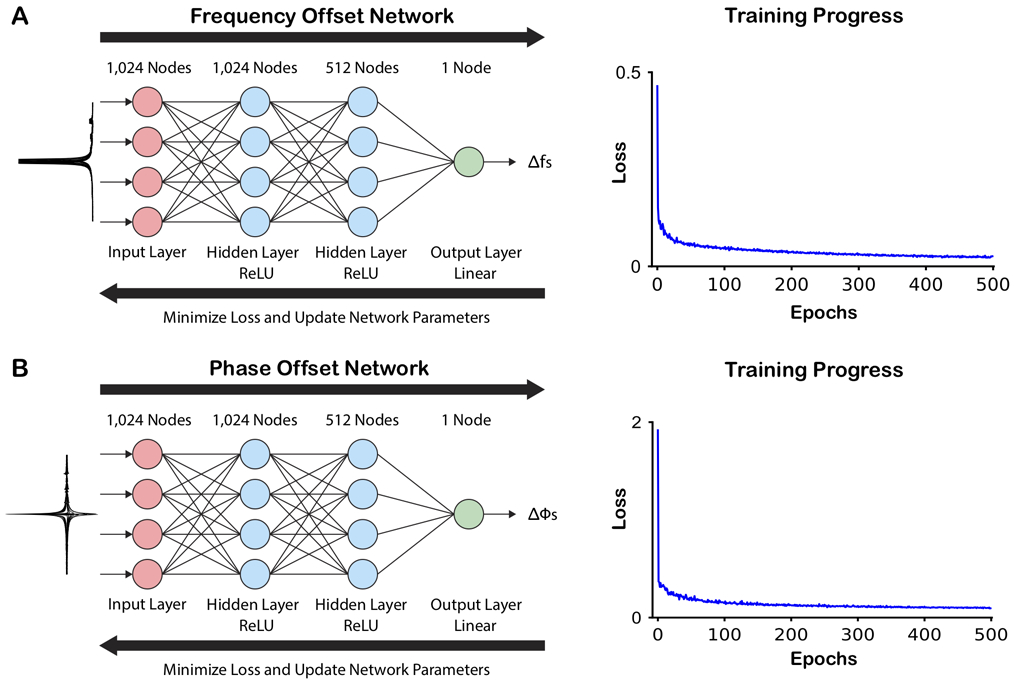
Figure 1.

Network structure and training progress. Both the frequency (A) and phase (B) offset networks have the same basic structure with three fully connected (FC) layers (1024, 512, 1 node(s)). The two hidden FC layers were each followed by a rectified linear unit (ReLU) activation function, and the output FC layer was followed by a linear activation function, which generated the output offset as a continuous variable. Simulated spectra manipulated with frequency offsets or phase offsets were used as training data for the respective network (illustrated on the left-hand of the figure). During the training, the loss between the predicted frequency/phase offsets and the true applied offsets were minimized, and the network parameters updated. Each network was trained through 500 epochs.
