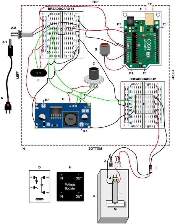
Figure 4. dTBI device wiring diagram:
The component labelling corresponds to the Materials section and Fig 3, the wiring and wire color correspond to the Device Construction section. A) Power supply, A.1) Male DC power supply plug, A.2) panel mount with female jack B) Buck converter, B.1) mounting holes for the standoff. C) Potentiometer D) SPST relay (larger version at the bottom with terminals numbered, and smaller version on Breadboard #1 with the terminal positions labelled in orange). E) Digital display F) Arduino, F.1) mounting holes for the standoff, F.2) 14x14mm square cutout in enclosure for Arduino USB G) Pushbutton H) Proportional voltage booster (larger version at the bottom with terminals labelled, and smaller version on Breadboard #2 with the terminal positions labelled in orange). I) Electrical terminal connector J) Spade terminal with washers (circle) and 4-40 mounting screw (hexagon). Larger version showing connections from electrical terminal connector and piezoelectric, and smaller version showing the positioning of the screws on top of the piezoelectric, with the washers and spade terminal underneath the piezoelectric. K) Polycarbonate base L) Piezoelectric actuator M) Heisenberg collar with fly N) Enclosure

