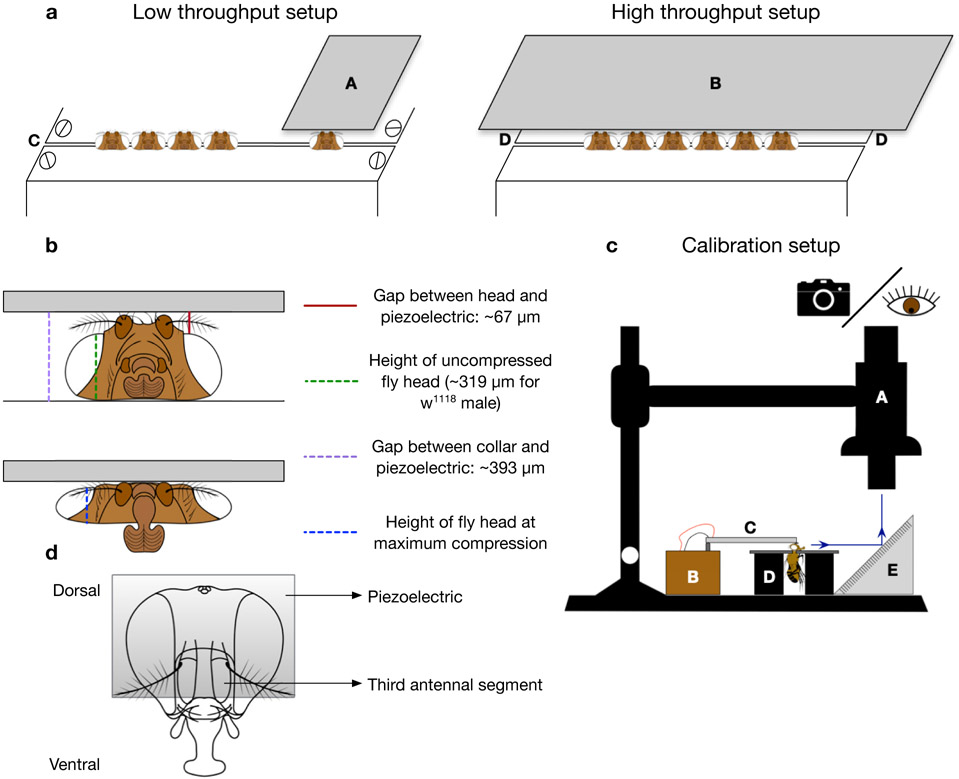
Figure 5. dTBI device setup and calibration:
a. Schematic of low-throughput and high-throughput dTBI devices. A) Narrow piezoelectric (Q220-A4-203YB from piezo.com) B) Wide piezoelectric (Q220-A4BR-2513YB from piezo.com) C) Classic or metal Heisenberg collar with space between plates set to 125μm D) Metal Heisenberg fly collar. b. Frontal schematic view of uncompressed fly head (above) and severely compressed fly head (below). The location and average value of various measurements are indicated and correspond to the representative measurements in Supplementary Video 2. c. Schematic of the setup for calibration of dTBI device. A) APO16 macroscope for viewing or taking videos B) dTBI controller circuit C) Piezoelectric D) Modified Heisenberg fly collar E) Mirror angled at 45°. d. Schematic of fly head depicting appropriate positioning of the piezoelectric relative to the third antennal segment

