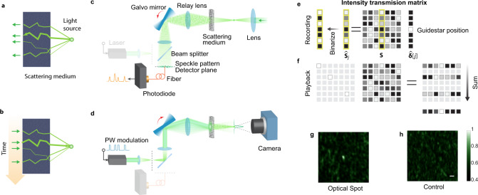
Fig. 4. Optical intensity transposition.
a, b The principle of optical intensity transposition. a Light emitted from a coherent light source at the target plane traverses the optical channels to the input plane. By measuring the light intensity of the transmitted light as a function of space, we can obtain a spatial map of the optical channels. b By sending light back through the bright channels and linearly combining the transmitted light, we can obtain a focus pattern at the source location. c, d Experimental setup. Similar to optical phase conjugation, the retroreflecting process can be separated into two steps. c Recording. A point source transmitted light through the scattering medium and a photodiode measures a one-dimensional speckle pattern during one galvo mirror sweep. d Playback. The measured signal is time-reversed and then modulates the laser on the input side as the galvo mirror scans backward. An optical spot is created at the position of the initial point source. e, f Matrix representation of optical intensity transposition. During recording e, a guidestar selects a column of the intensity transmission matrix as a time-varying intensity output, which is then binarized. During playback (f), the binarized signal is used to select the corresponding rows of the intensity matrix, whose sum leads to a bright optical spot at the guidestar position. g, h Experimental results. An optical spot pattern was imaged on a camera with optical intensity transposition (g), while no bright spot was observed in the control experiment where we disabled the synchronization between the playback sequence and the galvo mirror (h). Scale bar: 20 μm.

