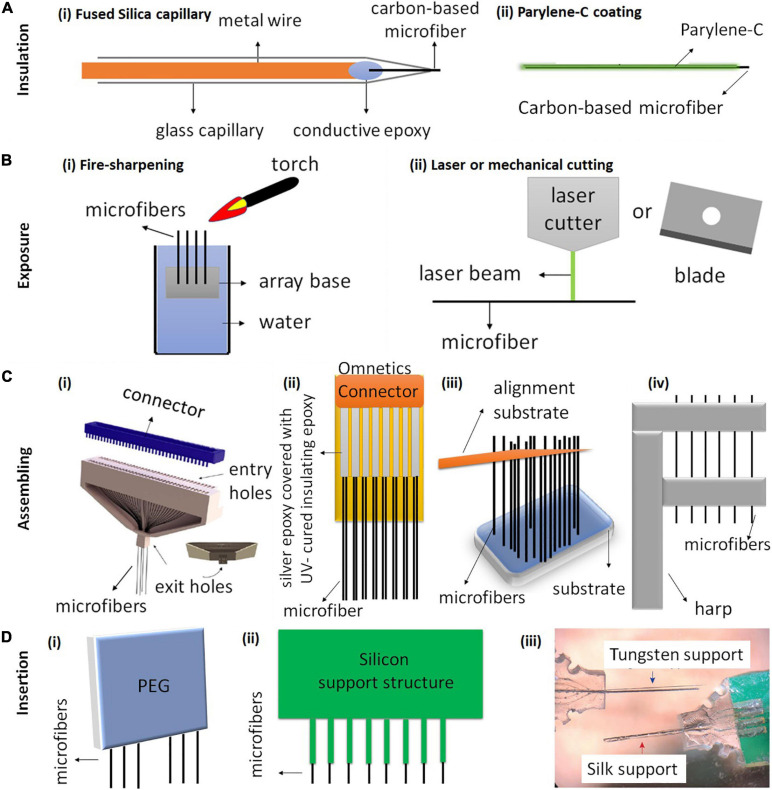
FIGURE 3.
Schematic illustration of carbon-based microfiber electrode array fabrication. (A) The most common methods for insulating carbon-based fiber electrodes use either (Ai) fused silica capillary or (Bii) Parylene-C coating. (B) Methods for exposing the electrode tips include (Bi) fire-sharpening and (Bii) laser or mechanical cutting. (C) Four different techniques have been used to assemble single fibers into electrode arrays. (Ci) A 64-channel carbon fiber array fabricated using a 3D-printed block (gray) for aligning the microfibers. Reproduced from Guitchounts and Cox (2020) with permission from the copyright holder. (Cii) An electrode array with 16 CFs, 8 on each side. The CFs are attached on a PCB board using silver epoxy and the PCB board is soldered onto an Omnetics connector. Reproduced from Patel et al. (2020). (Ciii) of a threaded device during assembly. An alignment substrate separated from the device substrate is used to parallelize the 2.5 mm-long fibers. Reproduced from Massey et al. (2019) (Civ) Fibers are aligned using a harp-like structure fabricated by 3D printing and laser writing. Reproduced from Gillis et al. (2018). (D) Three different insertion methods for inserting CF arrays. (Di) A poly (ethylene glycol) (PEG) coating can facilitate the insertion of CF arrays by temporarily stiffening the fibers. PEG dissolves after application of sterile Ringer’s solution (Patel et al., 2015). (Dii) A silicon support structure with shanks and CFs secured within the shanks (Patel et al., 2015). (Diii) CF electrode arrays with tungsten supports and silk supports. Reproduced from Lee Y. et al. (2019).

