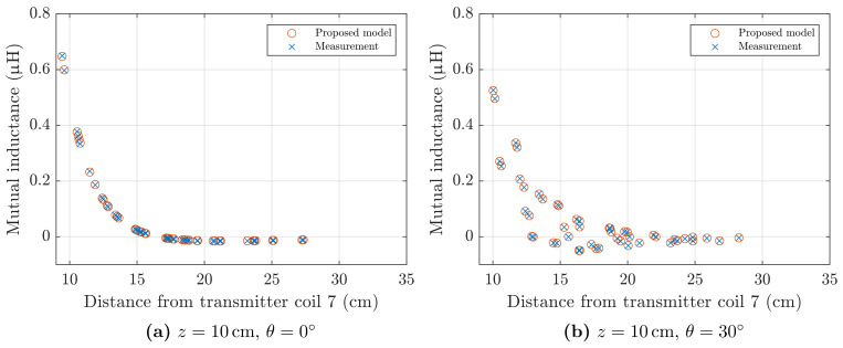
Figure 11.
Mutual inductance between coil a of Figure 8a, and transmitter coil 7 of the field generator, as defined in Figure 10a. Experimental values are compared to those predicted by the analytical model of Section 2. (a) Test points at 10 from the planar field generator, pitch angle . (b) Test points at 10 from the planar field generator, pitch angle .

