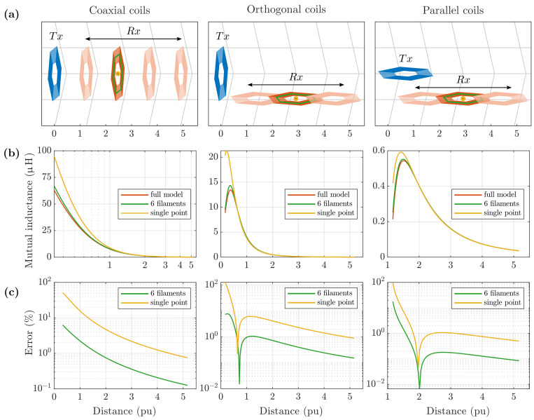
Figure 12.
(a) A transmitter coil, , and a receiver coil, , at increasing distance, for three orientation configurations. Plots are on a per unit (p.u.) scale, referring to the coil diameter. (b) The mutual inductance was calculated with the full model, 6-filament and single-point approximations. (c) The relative error falls below 1% at a distance of larger than 2 and 5 for the 6-filament and single-point models, respectively, for all the three orientations considered.

