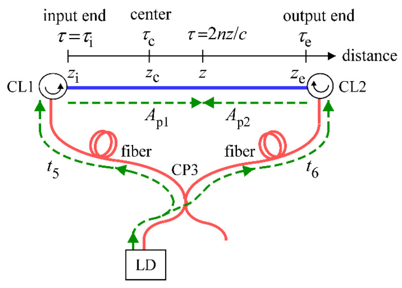
Figure 3.
Schematic of the propagation (highlighted in green) of counter-propagating pump light waves from the LD in the fiber loop. t5 and t6 are the propagation times of the pump light waves from the LD to optical circulators CL1 and CL2, respectively. z is a coordinate of the distance along the fiber under test highlighted in blue and the origin of the distance is positioned at the point where the produced reflection has the same optical path length as the LO light at the balanced mixer. The input and output ends of the fiber were assumed to be located at zi and ze, respectively. τ is the round-trip time from the origin to any position at z as defined by τ = 2nz/c, where n is the refractive index of the fiber and c is the velocity of light in a vacuum. Similarly, τi and τe are defined as τi = 2nzi/c and τe = 2nze/c. Ap1 and Ap2 are the complex amplitudes of the electric fields of the pump light waves propagating in the clockwise and counterclockwise directions, respectively. The center of pumping is defined by the position where the optical path lengths of the two pump light waves are equal in the optical fiber loop. CL1 and CL2: Optical circulators, CP3: Fiber coupler, LD: Laser diode.

