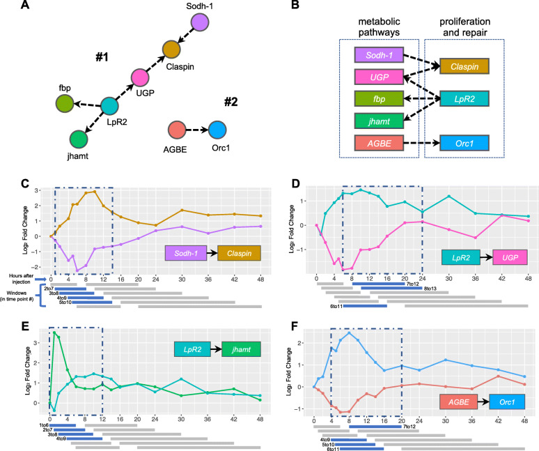
Fig. 9.
High-quality GC network components and their edges. a Components #1 and #2 from GC network (Figure S4). b Diagram summarizes interplay between main represented pathways on the selected components. c-f Selected edges from the components plotted against time. Significant windows colored in blue, non-significant colored in grey. Resulting overall consecutive windows are labeled in blue dashed rectangles. Individual windows represent 6 consecutive time points, but because time points are not at regular intervals, the windows have different time ranges, but identical numbers of samples

