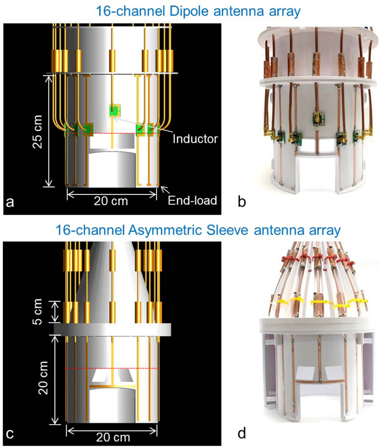
Fig. 2.

3D modeling (a and c) and photographs (b and d) of the 16-channel dipole and the 16-channel asymmetric sleeve antenna arrays. Importantly, all coaxial cables were included in the simulation to calculate E- and B-fields. Red dotted lines in Fig. 2a and 2c indicate the location of the individual transmit field maps displayed in Fig. 4c and 4f, respectively.
