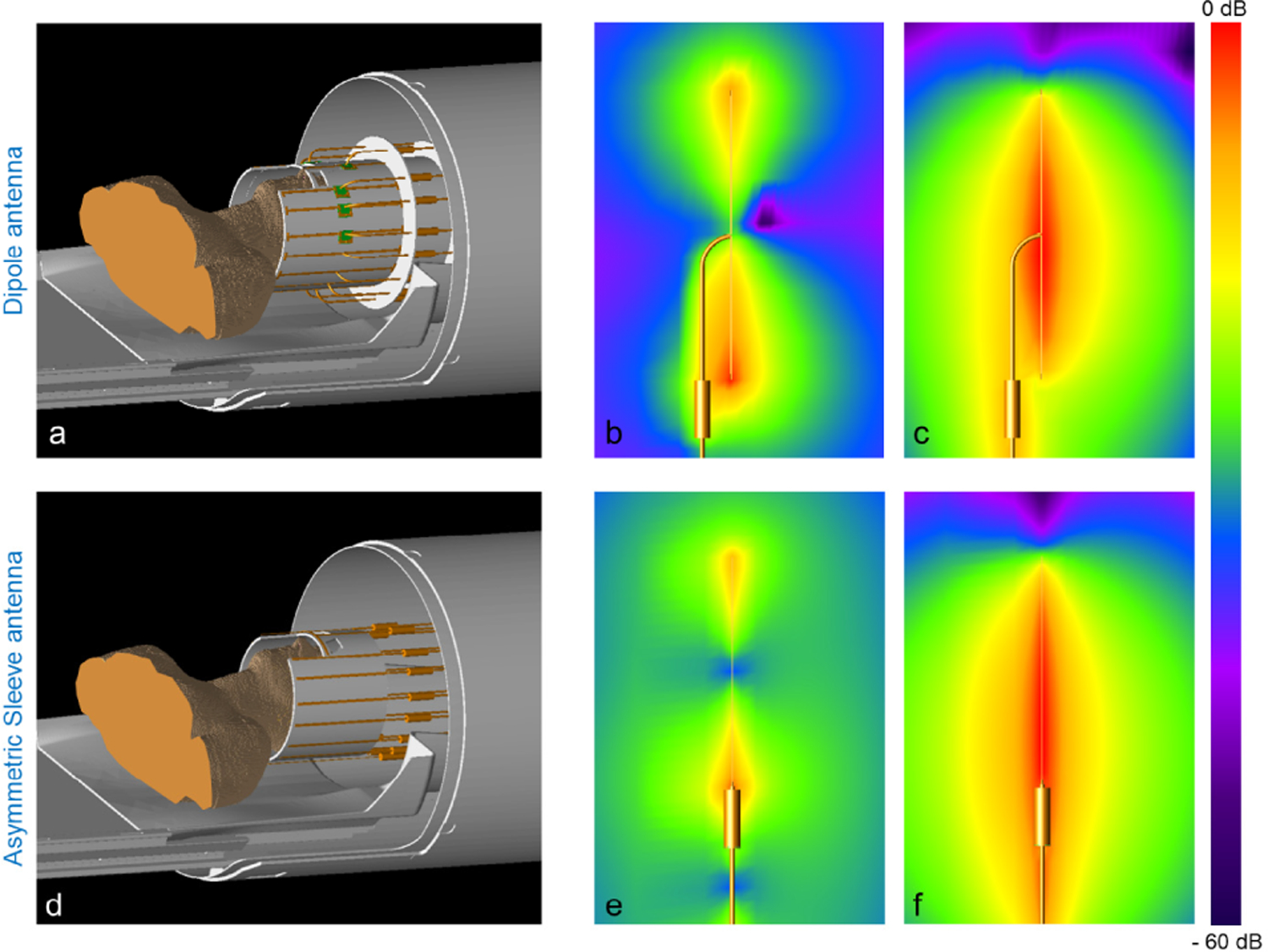
Fig. 3.

Simulation model of a dipole antenna array (a) and an asymmetric sleeve antenna array (d) with coaxial cables in the bore of the MRI system. For realistic head imaging, coaxial feed cables have to be positioned in parallel alignment with antennas for an in bore setup. Individual E-fields in free space including simulation of the coaxial cable of one dipole antenna (b) and one asymmetric sleeve antenna (e) are shown. Also shown are corresponding B-fields of one dipole antenna (c) and one asymmetric sleeve antenna (f). Note the higher interaction of the dipole antenna array with the center-fed coaxial cable, which results in high E- and B-fields between one pole of a dipole antenna and a coaxial cable (b and c). However, this is notably minimized in the asymmetric sleeve antenna (e and f).
