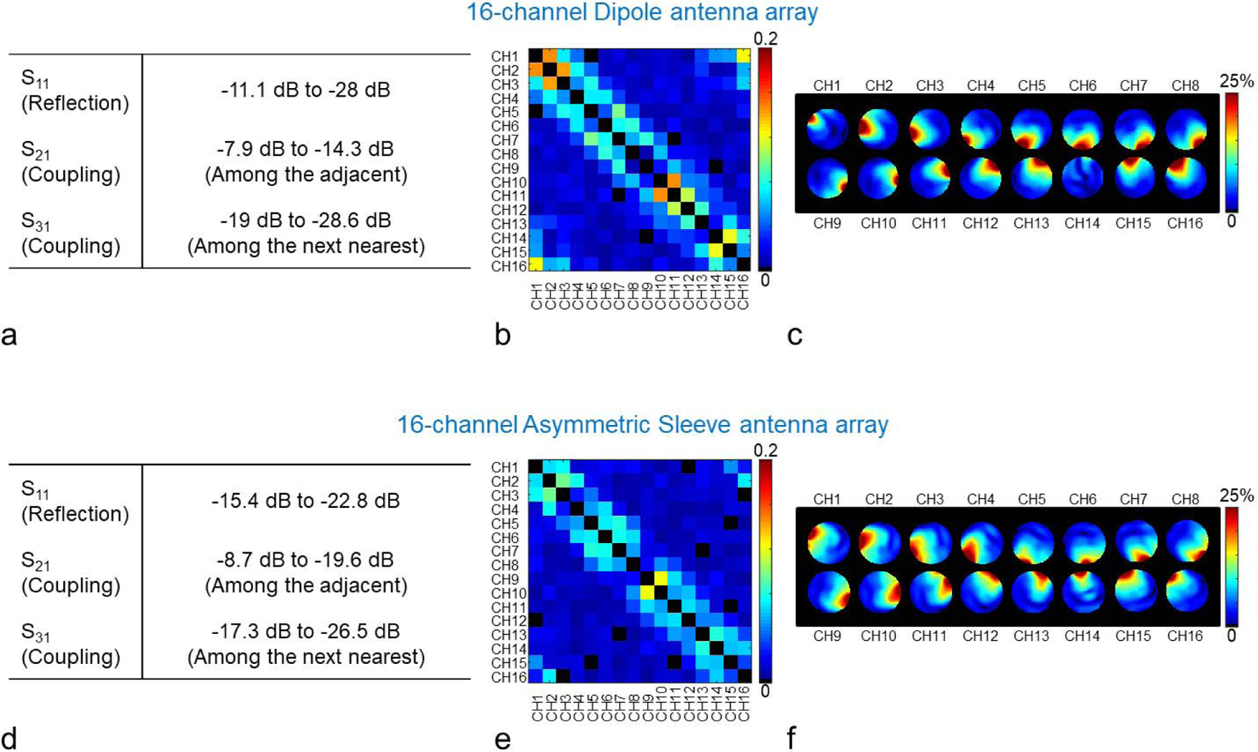
Fig. 4.

Summary of the achieved S-parameters (a and d), noise covariance matrices (b and e) and individual relative B1 magnitude maps (c and f) of the 16-channel dipole (upper row) and the 16-channel asymmetric sleeve antenna (lower row) arrays. Fig. 4c and 4f show relative percentage contribution of each transmitter on each pixel. Note that neither of these radiative arrays have any additional decoupling circuitry. As marked in Fig. 2a and 2c, the transmit field of dipole channel 14 (Fig. 4c), which is positioned over the forehead, appears weaker due to a shifted location and the larger inductors required for this shortened element.
