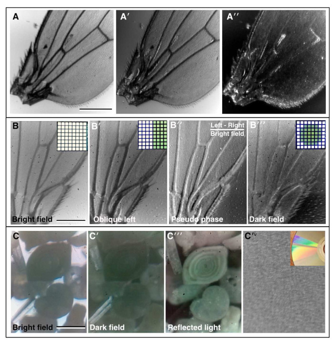
Figure 2. Bright field imaging modes.
( A–A′′) A fruit fly ( Drosophila melanogaster) wing imaged under direct illumination bright field (x10 lens, 0.25 NA) ( A) and different angles of oblique illumination ( A′, A′′) using the auxiliary flexi-lamp illumination. ( B–B′′) A fly wing imaged under different contrast methods using the bright field LED array (x10 lens, 0.25 NA): ( B) bright field, ( B′) oblique illumination, ( B′′) dark field, ( B′′′) pseudo-phase. Inset in B–B ′′′, the LED configuration used to generate the different contrast effects in each case. ( C–C′′′) Imaging a “fossil sand” sample from Dog’s Bay (Donegal, Ireland) in bright field; ( C) dark field and ( C′′) by reflected light (x4 lens, 0.12 NA). Several different microfossils are clearly visible. ( C′ v ) Reflected light imaging of a completely opaque sample: the tracks on a DVD (x25 lens, 0.35 NA), inset, photograph of the DVD showing the reflection grating colour pattern caused by the tracks. (Scale bars = 0.3 mm in A, 0.22 mm in B and 0.25 mm in C.)

