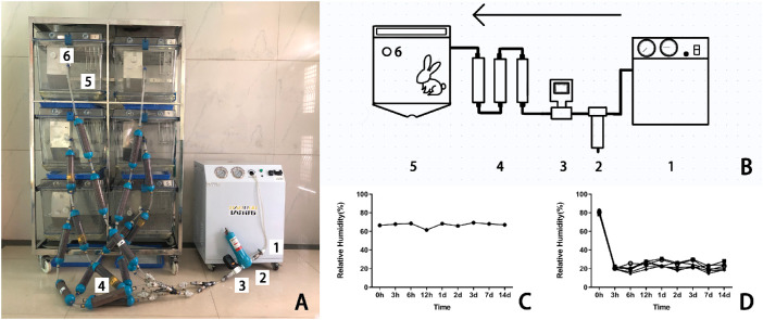
Figure 1.
The real and illustrative structure of the CDS. (A) The CDS consisted of (1) an air pump, (2) a compressed air fine filter, (3) a flowmeter, (4) dry columns packed with desiccants, (5) a modified rabbit cage, and (6) a humidity recorder. (B) Schematic diagram of the CDS. The devices labeled 1 to 6 are referred to the same in the photograph A. (C) The RH of the air in the control group was steadily kept between 60% and 70%. (D) The RH of the air in the dry group was maintained at 22% ± 4%.

