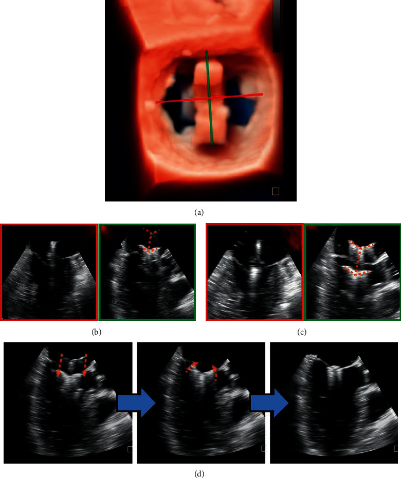
Figure 4.

Advancement and adjustment of the clamp. 3D enface view (a) and X-plane view (b) show that the clamp is located in the center of the MV orifice and perpendicular to the MV closure line. The full length of the clamp arms (c) (orange dotted line) is seen in the long-axis view, and in the ME-commissural view, no clamp arms but the delivery rod should be seen. Next, the rear clamp is retracted into the LV, and the clamp orientation is reassessed with lowered gain settings (right: oblique perspective). (d) Leaflet Grasping.
