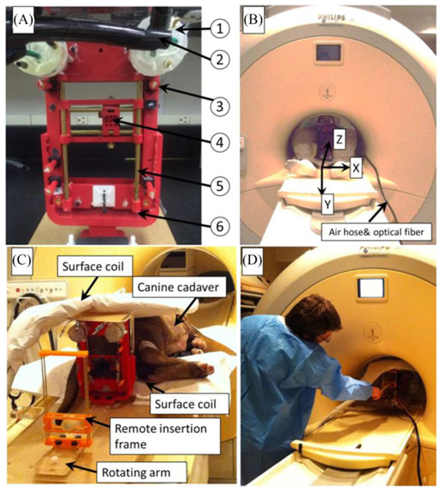
Fig. 1.
(A) Prostate robot assembly. The detailed parts can be listed as follows: (1) custom designed pneumatic motor; (2) air hose bundle; (3) fiducial markers; (4) movable template; (5) supporting rod. (b) Prostate robot and volunteer inside the MR scanner. MRI coordinate frame is also shown. (C) Prostate robot and manual insertion mechanism for the canine cadaver study inside the MRI room. (D) User manually inserts the needle toward the target.

