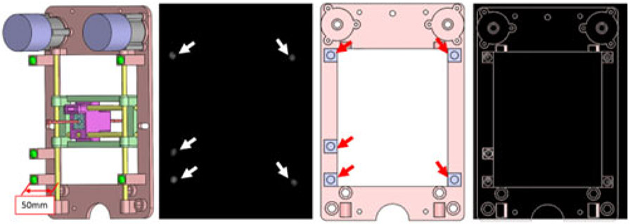
Fig. 4.
From left to right: fiducial marker positions with respect to the robot frame with the offset of 50 mm perpendicular to the transverse plane of the robot to eliminate the effect of brass rod. Green balls show the five fiducial markers; MR image of the robot frame. White arrows: five fiducial markers within the MR image; front view of the prostate CAD model with fiducial markers labeled on the transverse plane. Red arrows: fiducial marker positions on the robot frame; MR image overlaid on the robot CAD design.

