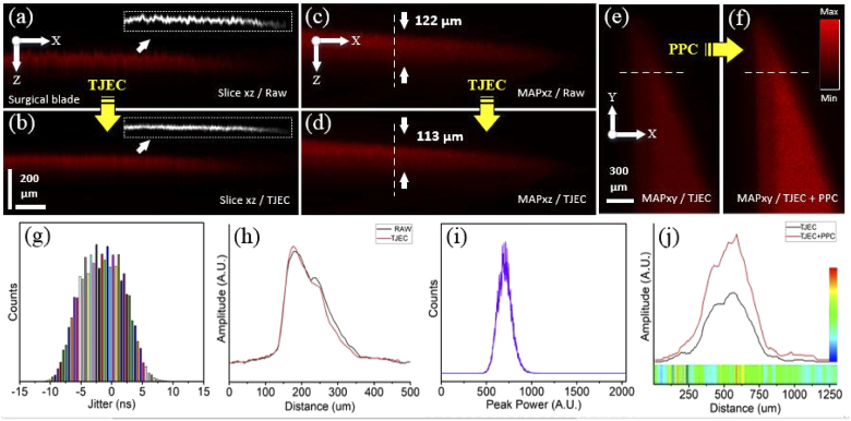
Fig. 6.
Results of timing jitter effect correction and pulse peak-power compensation for the PA images of the surgical blade sample. (a, b) are the B-mode images of raw and TJ effect corrected signals and their corresponding surface edges, (c, d) the MAPxz images of raw and TJ effect corrected signals, and (e, f) the MAPxy images of TJ effect corrected and TJ effect corrected plus PP compensated signals. (g, i) illustrate the laser TJ and PP histograms and (h, j) are intensity profiles on the dashed lines in (c, d) and (e, f). The horizontal colored ribbon in (j) indicates the PP enhancement factor for any pixel and the vertical color-bar is the scale-bar of the PP enhancement factor.

