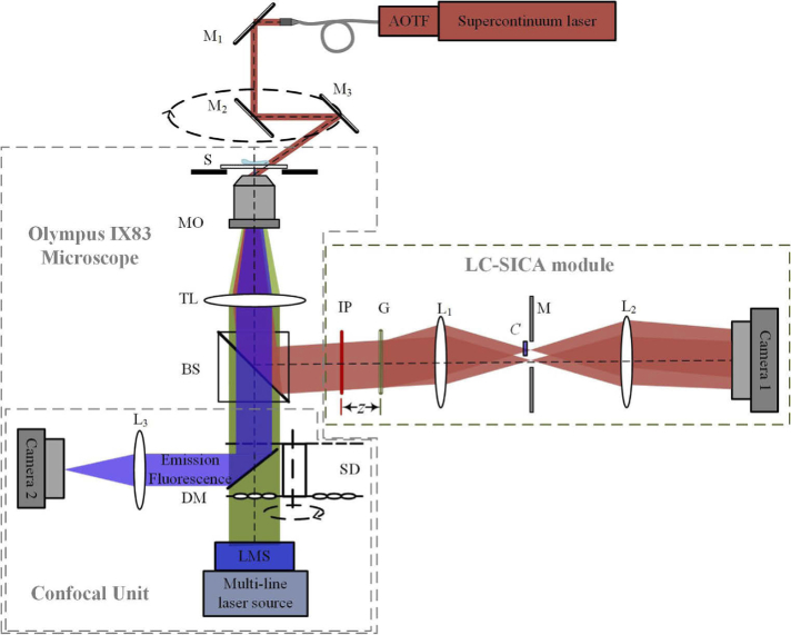
Fig. 1.
Simplified schematic diagram of the combined TPM-SDCM system. The TPM beams appear in dark red; the fluorescent excitation beams appear in green and the fluorescent emission beams appear in blue. The LC-SICA module is placed at the output of an IX83 microscope for low-coherence phase imaging. The scanning confocal unit is for 3D fluorescent imaging. AOTF, acousto-optic tunable filter; M1, M2, M3, mirrors; S, sample; MO, microscope objective; TL, tube lens; BS, beam splitter; IP, image plane; G, grating; L1, L2, lenses with focal lengths f1=150 mm and f2=300 mm. z, distance of G from IP; M, mask that selects only two diffraction orders; C, compensating plate; SD, spinning disk; DM, dichroic mirror; L3, relay lens; LMS, laser merging module.

