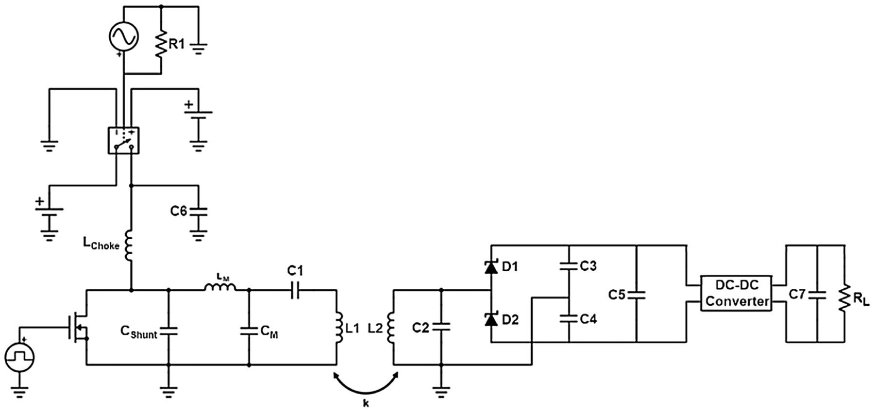
FIGURE 4.

On the left, the simulated circuit model of the transmitter, consisting of a class E power amplifier (Lchoke = 220 μH, Cshunt = 180 pF, and BS170 MOSFET), matching circuit, and series tank circuit. On the right, the simulated circuit model of the receiver, consisting of a parallel tank circuit, rectifier, and regulator. The circuit was modeled using coil properties and coupling coefficient obtained from the ANSYS simulations.
