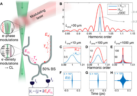
Fig. 3. Correlations in the CL into a dielectric waveguide produced by modulated electrons.

(A) Conceptual scheme of the experimental setting on the basis of photonic circuitry. A laser field structures a pulsed electron beam, which excites coherent radiation in a parallel-aligned waveguide. Mixing a replica of the driving laser field, ER, with the CL field, ECL, results in a difference between the signals recorded in the detectors at the output ports of the interferometer, I1 and I2. (B) Properties of CL emitted into the waveguide for an interaction length of 30 μm positioned at a distance z = 6.43 mm away from the electron modulation region. The coherent CL amplitude (blue) is the product of the spectral coupling amplitude, ∣gω∣ (red), and (gray), where phase matching between the electron and the guided modes limits the CL emission to a single harmonic peak. (C) to (H) show CL properties as a function of the propagation length near the fiber, Lprop: (C) to (E) show the spectral distribution of ∣gω∣ and , whereas (F) to (H) show the emitted CL-field pulse in the time domain, E(t). The different columns show the CL properties for an electron propagation length Lprop = 10 μm (C and F), 100 μm (D and G), and 1 mm (E and H) along the waveguide. The effect of Lprop on the peak probability of emission is reflected in the vertical scale. When the coupling bandwidth is narrower than the width of the DOC [e.g., in (E)], the CL pulse is temporally distorted (H). Details of the coupling into a cylindrical waveguide are presented elsewhere (36).
