FIG 3.
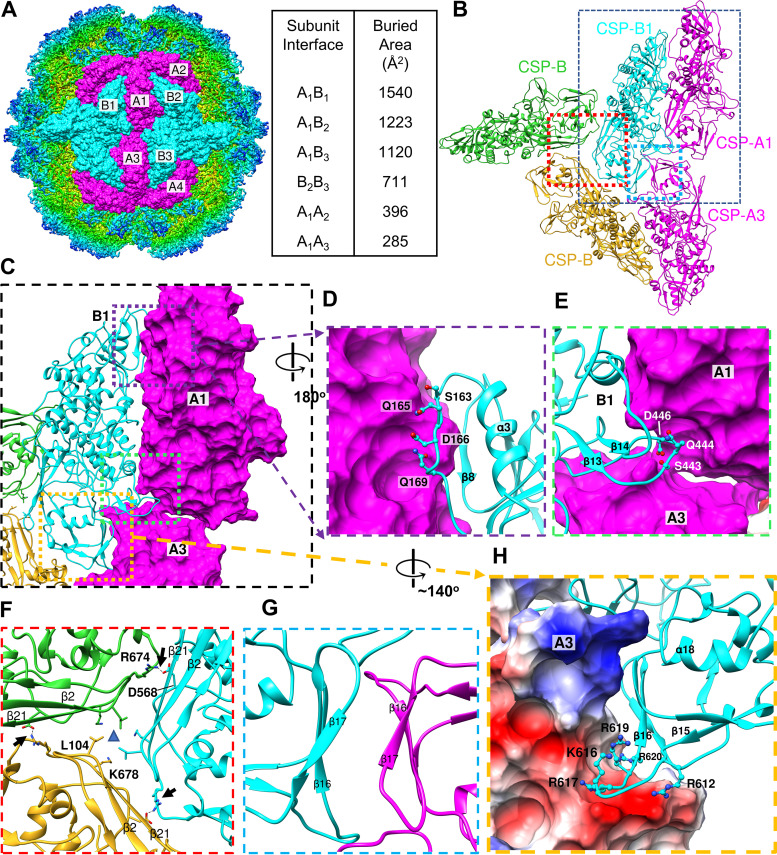
CSP interactions coordinate capsid structure. (A) Six copies of both CSP-A and CSP-B conformers fit into the TVV2 cryoEM map as viewed down the axis of I2 symmetry. Buried surface area (Å2) between subunit interfaces are listed at right. (B) Ribbon diagram of TVV capsid proteins illustrating contact surfaces between two CSP-As (magenta) and 3 CSP-Bs belonging to different decameric units (cyan, green, goldenrod). (C) Closer view of B1A1 interface with A1 and A3 surfaces displayed to illustrate contacts. (D) Close-up view of the unwound α4 of CSP-B with involved CSP-B residues shown. (E) View of the unwound α15 of CSP-B inserting beneath the long helices of the viral carapace domain. (F) View down 3-fold axis with residues involved in 3-fold symmetry position shown. (G) Opposing β-strands with β17 from both CSPs demonstrating slight twist toward β-sheet like character. (H) Electrostatic potential surface map displaying the positively charged residues of the β15-β16 loop of CSP-B, fit into the negatively charged (red) pocket between carapace and dimerization domains of CSP-A.

