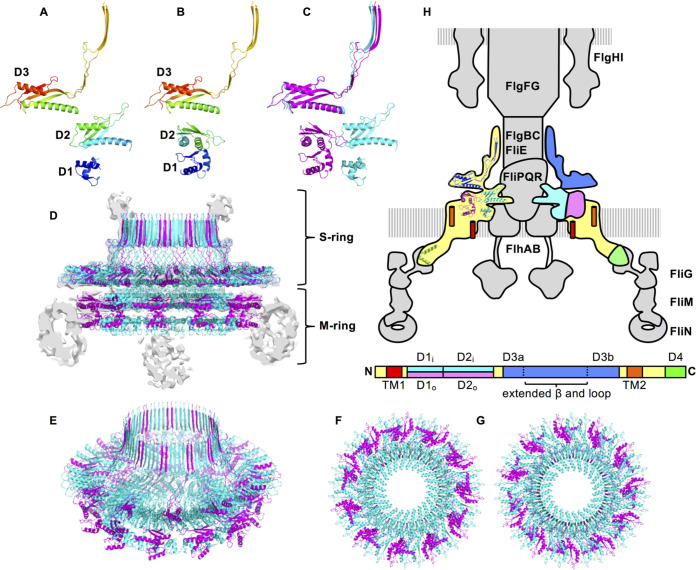
FIG 4.
The structure model of the periplasmic region of the MS-ring. (A, B) The two distinct conformations of the FliF subunit in the MS-ring. (A) The structure of the FliF subunit that forms the inner ring (A) and the middle region (B) of the M-ring and the S-ring. (C) Superimposition of A (cyan) and B (magenta). (D to G) Structure of the periplasmic region of the MS-ring. The side view (D), the diagonal view (E), the bottom view (F), and the top view (G) are shown in the same color profile as in C. The gray image in D is the vertical section of the cryoEM density map. (H) Arrangement and location of FliF in the flagellar motor. The MS-ring is colored, and the others are shown in gray in the schematic drawing of the flagellar basal body. The primary structure of FliF with the domain annotation is shown below the basal body. The ribbon model of FliF is overlaid on the left half of the MS-ring. The right half of the MS-ring is colored as in the domain annotation of the primary structure. Green represents the C-terminal region of FliF from Thermotoga maritima (PDB ID: 5TDY) (40).

