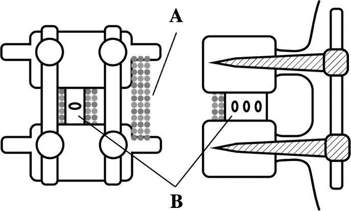
Figure 1.

Diagram illustrating a single-level fusion with instrumentation and different options for placement of bone graft material (left: posterior view; right: lateral view). (A) Demonstrates an intertransverse fusion with graft material placed between the transverse processes of adjacent vertebral levels. (B) Demonstrates an interbody fusion with a cage containing graft material placed in between the vertebral bodies of adjacent levels.
