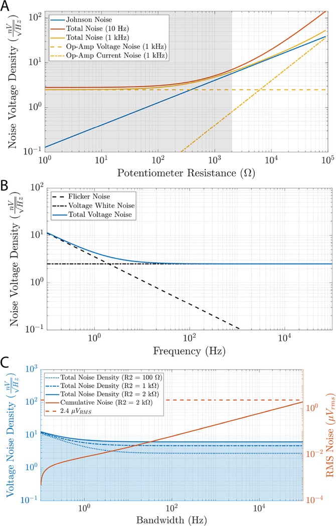
Figure 3.
(A) A low voltage noise op-amp was chosen as the output buffer because this type of noise dominates in the operating regime of the circuit. A comparison is given between the voltage and current noise of the LT1007 op-amp and the Johnson noise of the voltage divider circuit for different settings of the potentiometer (switched resistor at 1 MΩ) at 1 kHz. The shaded region represents the range of resistances available for the 2 kΩ potentiometer used in NeuroDAC. Theoretical total noise accounting for all of these sources is also shown at 10 Hz and 1 kHz. (B) The full theoretical voltage noise spectrum of the LT1007 op-amp including low frequency flicker noise. (C) The total estimated noise spectra of the NeuroDAC analog circuitry at potentiometer settings of 100 Ω, 1 kΩ, and 2 kΩ. Cumulative RMS noise is indicated in blue as the bandwidth of the system is selected from 0.1 Hz to the value indicated on the horizontal axis. The shaded blue region indicates the integral area underneath the noise density curve for the worst-case 2 kΩ potentiometer setting. A dashed line indicates the reported noise floor of the Intan RHD2132 biosignal amplifier for reference (2.4 μVrms [41]).

