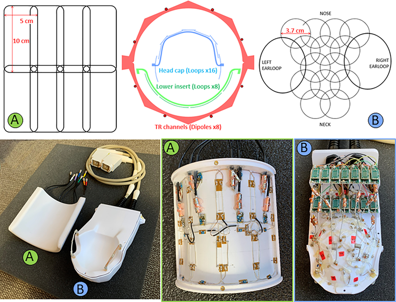
Figure 2:
Axial cross-sectional diagram (top-center) of the coil arrangement for the dipole transmit/receive (TR array), 8-CH receive lower insert (A) and 16-CH receive headcap (B). Loop arrangements for the receive arrays are shown for the headcap (top-left) and lower insert (top-right). Also shown are housing and coils (bottom) for the lower insert (A) and headcap (B). One can also see the preamplifier boards arranged in two rows behind the head cap (bottom-right).

