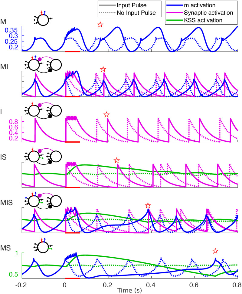
Fig 8. Buildup of outward currents in response to input pulses.
Activation variables (color) plotted for simulations both with (dotted lines) and without (solid lines) an input pulse lasting 50 ms. Red bar indicates the timing of the input pulse; red star indicates the time of the first post-input spike.

