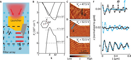
Fig. 2. Directional launching of Bloch polaritons.

(A) Schematic of the device with the scanned region marked in the dashed box. The shades of blue colors represent different carrier densities in graphene. (B) Dependence of the polariton momentum k on average carrier density at ω = 890 cm−1. Dashed lines correspond to the experimental conditions in (C) to (E). Inset: BZ of the polaritonic crystal marked with symmetry points. (C) Near-field image acquired at T = 60 K and Vg = 47.5 V. Bloch polaritons propagate in direction, as marked by the black arrow. (D) and (E) same as (C) at Vg = 52.5 V and Vg = 72.5 V, respectively. (D) shows that Bloch polaritons propagate predominantly in direction, as marked by the cyan arrow. (E) reveals isotropic polariton propagation in all directions. (F) Averaged line profiles along and directions acquired from (C) to (E). Line profiles are normalized to gold and shifted vertically by multiples of 0.02 units for clarity.
