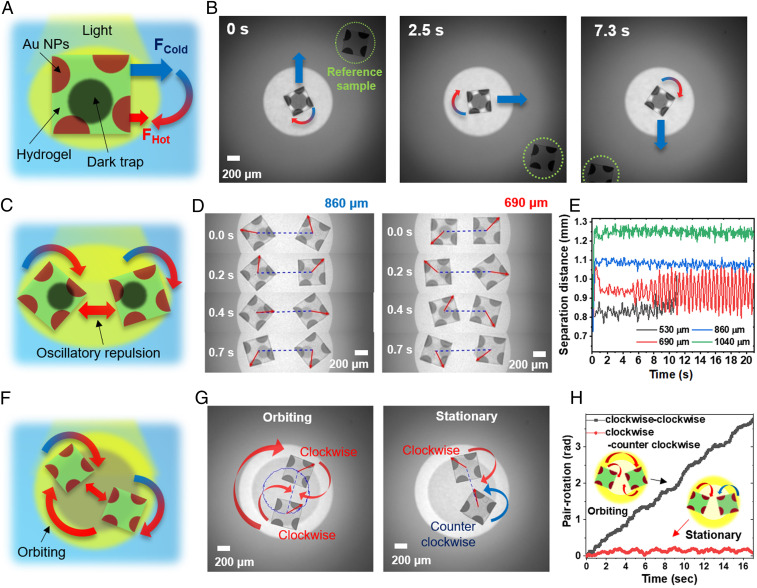
Fig. 4.
Active HND spinners. (A) Schematic diagram of square-shaped HNDs containing chiral Au NP patterns to create light-driven spinners. (B) Time-lapsed images showing rotational and translational motions with moving trap pattern (Movie S4). (C) Schematic diagram of HND spinners coupled by two trap patterns. (D) Time-lapse images of spinning HNDs trapped with center-to-center separation distances of 690 and 860 μm. (E) Separation distances of the centers of HNDs versus time. (F) Schematic diagram of HND spinners in a circular well. (G) Images of two clockwise rotating HNDs (Left) and clockwise and counterclockwise rotating HNDs (Right) under circular optical confinement (Movie S5). (H) Pair-rotation angles versus time for the same and opposite-directional HND spinners under optical confinement.

