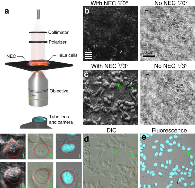
Fig. 4. Phase-imaging HeLa cells.

a The experimental arrangement—637 nm light is collimated and polarised with the electric field parallel to the grating lines before passing through a Petri dish containing fixed HeLa cells above the NEC. On passing through the NEC the light is collected by a ×20 objective and imaged onto a camera. b, c Images obtained for the same region of cells with and without the NEC at two different tilts with respect to the incident light b no tilt Θ = 0°, c tilt Θ = 3°. The regions labelled 1 and 2 are magnified in the inset. Grating orientation and incident polarisation as indicated by inset in b. d Conventional microscope images of the same cells using DIC (left panel) and fluorescence (right panel). The blue regions in the fluorescence image highlight the cell nuclei. Inset: Enlargements of the images obtained by the NEC at Θ = 3° tilt, the DIC and fluorescence microscopes as indicated by the numbers. The circles highlight nucleoli inside the nucleus of each cell
