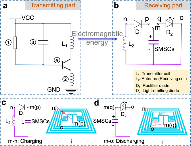
Fig. 4. Circuit diagram and working mechanism of the wireless charging system.
a Circuit diagram of wireless transmitting part and (b) receiving part. c Schematics of the circuit while connecting points “m” and “p” of IWC-SMSCs to charge SMSCs (i). d Schematics of the circuit while connecting point “m” and “q” of IWC-SMSCs to release the accumulated charges in SMSCs (ii), thus lighting a red LED. The IWC-SMSCs are in purple color in the circuit diagrams.

