| Recent static in vitro biofilm models |
|
|
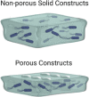
3D bioprinted biofilm construct (Ning et al., 2019)
|
 |
|
|
E. coli clinical isolate (American Type Culture Collection [ATCC] 25922), methicillin-resistant S. aureus (MRSA, clinical isolate, ATCC 700788), methicillin-sensitive S. aureus (MSSA, clinical isolate, ATCC 29213) P. aeruginosa, PAO1 (wild-type strain, ATCC 47085) |
-
•
Customizable predesigned biofilm thickness and dimensions
-
•
Construct stability for up to 4 weeks
-
•
Adequate cell viability
-
•
Suitable for aerobic and anaerobic biofilms
-
•
Allows biofilm formation monitoring
-
•
Suitable for antimicrobial testing (biofilm penetration and eradication)
-
•
Greater antimicrobial resistance than 2D cultures
-
•
Cost effective
|
-
•
Constructs with thickness of 0.5 mm or thinner are structurally unstable
-
•
Missing interaction with cellular and molecular components
-
•
Decreased cell density as thickness increases
-
•
Restricted to biofilms grown in semisolid conditions
|
|
|
Patterned SLIPS (“slippery” lubricant-infused porous surface) (Bruchmann et al., 2017)
|
 |
|
Biofilm screening Antimicrobial testing |
|
-
•
Control over the biofilm microcluster geometry
-
•
High reproducibility
-
•
Biofilm stability
-
•
Allows the study of interactions between biofilm subpopulations
-
•
Suitable for drug screening
|
-
•
Biofilm formation by different bacterial strains may be influenced by the size and arrangement of SLIPS microclusters
-
•
Interactions between biofilm clusters
-
•
Missing interaction with cellular and molecular components
|
|
The dissolvable bead (Dall et al., 2017)
|
 |
|
|
MSSA S. aureus (ATCC #29213), S. mutans (NCTC #10923), E. coli (ATCC #25922), clinical isolates of coagulase-negative Staphylococcus (CNS-J), E. faecalis, K. pneumoniae, and P. aeruginosa |
-
•
Localized biofilm formation onto the alginate bead surface
-
•
Uniform exposure to antimicrobials
-
•
Undisrupted biofilm
-
•
Suitable for drug screening
-
•
Greater assay responsiveness than the crystal violet assay to an antibiotic challenge
-
•
Rapid and reproducible
-
•
Cost efficient and time efficient
|
-
•
Formed beads are not regular in size and shape
-
•
Potential influence of alginate beads architecture on biofilm phenotype
-
•
Homogeneous biofilm composition
-
•
Missing interaction with cellular and molecular components
|
|
|
Impedance-based multielectrode array (Goikoetxea et al., 2018)
|
 |
|
|
|
-
•
Nondestructive and label-free characterization of biofilms
-
•
Allows distinction of biofilms with structural differences
-
•
Able to identify attachment and maturation stages of the biofilm formation cycle
-
•
Good spatial resolution
-
•
Reduced sample volume
|
|
|
Vertical capacitance aptamer-functionalized sensor (Song et al., 2019)
|
 |
|
|
E. coli (ATCC 25922), P. aeruginosa (ATCC 27853), S. aureus (ATCC 29213), mutant strains Δpel and Δpel/Δpsl of P. aeruginosa strain PAO1 |
-
•
Real-time monitoring of biofilm formation
-
•
Biofilm formation and bacterial growth can be monitored simultaneously
-
•
Suitable for antimicrobial testing
-
•
Simple, flexible, and cost effective
-
•
Detection of low bacterial concentrations
|
|
|
|
Gold mushroom-like nanoplasmonic biochip (Funari et al., 2018)
|
 |
|
|
E. coli (MC4100). Cell density: Initial: 2 × 10⁷ CFU/mL Final: Not reported |
-
•
Real-time, nondisruptive, label-free monitoring of biofilm formation
-
•
High sensitivity
-
•
Allows comparisons between biofilm-forming species
-
•
Suitable for antimicrobial testing
-
•
Possibility of automatization for data acquisition during several days
|
-
•
Requirement of specialized equipment for device fabrication
-
•
Potential scattering in the LSPR signal if there is a high cell density per well
-
•
Sustained illumination may cause local stress to cells
-
•
Intermediate viability (65%)
-
•
Missing interaction with cellular and molecular components
|
|
Biofilm rheometer plate (Grumbein et al., 2016)
|
 |
|
|
|
-
•
Biofilm can be measured in its naturally grown state
-
•
Allows the evaluation of antimicrobials on biofilm structural resistance
-
•
Cost effective: reusable sample holders
-
•
Biofilm deformation during the test can be followed visually
|
-
•
Low force signal detection
-
•
Proper methods and filters must be applied to optimize the signal-to-noise ratio of measured data
-
•
Does not allow multiple biomechanical quantifications on the same sample
-
•
Missing interaction with cellular and molecular components
|
|
|
Human plasma biofilm model (hpBIOM) (Besser et al., 2020; Besser et al., 2019)
|
 |
|
|
S. aureus subsp. aureus (DSM 799), S. epidermidis (DSM 20044), P. aeruginosa (DSM 939), E. faecium (DSM 2146), and C. albicans (DSM 1386) Cell density: Initial: 2 × 10⁶ CFU/3 mL plasma solution Final (24 h): From 105 to 109 |
-
•
Resembles a human wound milieu
-
•
Incorporates immune system components: white cells, platelets, and complement system
-
•
Personalized antimicrobial testing (donor specific)
|
-
•
Results are not generalizable (effect is donor specific)
-
•
Pathogen-dependent stability
-
•
Does not include the damaged skin component of the wound: lack of skin cells
|
|
| Recent dynamic in vitro biofilm models |
|
|
Microcalorimetry flow system (Said et al., 2015)
|
 |
A heat exchange unit connects an external bioreactor to the stainless-steel ampoule of a commercially available calorimeter. The heat flow, which is associated with bacterial metabolic activity, is then related to changes in the power signal of the calorimeter as an indicator of biofilm formation
|
|
S. aureus (NCIMB 9518) Cell density: Initial: 106 CFU Final: 3 × 10¹⁰ CFU/mL |
-
•
Sensitive to reduced cell density and small changes in metabolic activity
-
•
Noninvasive & nondisruptive method
-
•
Suitable for real-time monitoring of biofilm formation
-
•
Simple and reusable (removable parts permit sterilization)
-
•
Versatile: Allows monitoring of bacterial activity and evaluation of the effect of antimicrobials in a wide range of tubing materials and medical devices/implants (does not require optical clarity of the sample)
|
-
•
Limited to low shear rates so as to not disturb the calorimeter
-
•
Large sized equipment
-
•
High costs for the calorimeter equipment
-
•
Complex data analysis
-
•
Limited throughput
-
•
Nonspecific: Heat flow signal involves the sum of a variety of processes taking place
-
•
It would require important adaptations if medical devices/implants are intended to be evaluated: should consider cellular and molecular interactions
|
|
Duckworth Biofilm Device (Duckworth et al., 2018)
|
 |
3D-printed device with four channels that provide nutrients to three circular wells each. An agar disk, in direct contact with the nutritious flow, rests onto each well and supports a cellulose membrane, resembling the air-liquid interface where the biofilm is grown
|
|
P. aeruginosa S. aureus Cell density: Initial: 105 CFU Final: ∼8–10 Log(CFU/mL) |
-
•
Mimics the air-liquid interface found in wounds
-
•
Allows temperature control and visual inspection without disrupting the biofilm
-
•
Has a lid and filter to prevent samples from crosscontamination
-
•
Good reproducibility and versatility
-
•
Small sized, inexpensive, reusable, and simple setup
|
-
•
Requires fairly large amounts of media (500 mL/24 h).
-
•
Level of exudate is not regulated
-
•
Missing interaction with cellular and molecular components
|
|
|
Flow chamber system for medical implants (Rath et al., 2017)
|
 |
|
|
-
(1)
S. gordonii (DSM, 20568)
-
(2)
S. salivarius (DSM, 20067)
-
(3)
P. gingivalis (DSM, 20709)
-
(4)
S. oralis (ATCC 9811)
-
(5)
A.actinomycetemcomitans (ATCC 2474)
Cell density: (CFU/mL, ×10 6)
Final: Not reported. Higher thickness: 38.85 μm for 7.88 × 10⁶ CFU/mL |
-
•
Mimics physiological flow conditions of the oral cavity
-
•
Setup can be adjusted to aerobic or anaerobic conditions
-
•
Direct microscopic observation of the implant surface is possible
-
•
Easy removal of implant samples
-
•
Minimization of detachment effects because of removable cover and discs
-
•
Fully autoclavable and reusable system
-
•
Reproducible
|
-
•
Culture conditions do not mimic the wide variety of nutrients found in the oral cavity
-
•
Optimization of conditions is necessary for the formation of multispecies biofilms
-
•
Missing interaction with cellular and molecular components
|
|
Flexible impedimetric detection platform (Huiszoon et al., 2019)
|
 |
|
|
|
-
•
Flexible nature of the platform allows its use in clinically relevant curved surfaces and potentially in other types of geometries
-
•
Compact size
-
•
Allows for real-time nondestructive monitoring of biofilm development
-
•
Suitable for evaluation of combined therapies/treatments
|
|
|
|
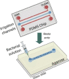
Microfluidic agarose channel device (Jung et al., 2015)
|
 |
|
Study of surface-free biofilms, similar to those formed within mucosal or viscous environments Testing of antimicrobial agents |
P. aeruginosa (ATCC 27853), E. coli (ATCC 25922), E. faecalis (ATCC 29212), S. aureus (ATCC 29213), B. subtilis (ATCC 6633), P. aeruginosa PA14 and its mutants wspF and pel Cell density: Initial: OD600nm ≈ 1.0 Final: Not reported |
-
•
Allows for direct microscopic investigation
-
•
Better mimics the environment found on shear-free clinically relevant intracellular- and mucosal-associated biofilms
-
•
Simple, small-sized, and inexpensive device
-
•
Full biofilm development cycle is reached in few hours (9–12 h)
|
-
•
Model not relevant to environments under shear stress
-
•
Maturation and integrity of ECAS is affected by fixing stress, viscosity, and nutrition
-
•
Missing interaction with cellular and molecular components
|
|
Microfluidic wound model (Wright et al., 2015)
|
 |
|
|
|
-
•
Small sized
-
•
Resembles concentration gradients of wounds
-
•
Viewing channels allow high-resolution imaging techniques for real-time monitoring
-
•
Allows identification of individual species in dual-species biofilms
|
|
|
|
Microfluidic artificial teeth device (Lam et al., 2016)
|
 |
|
|
|
-
•
Facilitates the real-time and long-term monitoring (≥1 weeks) of biofilm development
-
•
Ability to independently adjust several microenvironmental conditions in scheduled times
-
•
Allows quantitative determination of biofilm thickness, cell viability, and spatial distribution
-
•
Small-sized and inexpensive device
|
|


