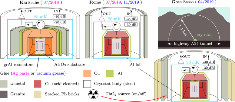
Fig. 2. Three different setups with various degrees of shielding against ionizing radiation.
Schematic half-sections of the setups, in Karlsruhe, Rome, and Gran Sasso, denoted K, R, and G, respectively. The measurement dates for each setup are indicated in the top labels. The sapphire chip is glued to a copper waveguide using either silver paste (K and R, magenta) or vacuum grease (G and R, blue). A circulator routes the attenuated input signal to the sample holder, and the reflected output signal to an isolator and an amplification chain (cf. Supplementary Information). In the R and G setups, the waveguide is etched with citric acid to remove possibly radioactive contaminants. The G setup, located under 1.4 km of granite (3.6 km water equivalent) is operated in three configurations. First, the cryostat is surrounded by a 10 cm thick wall of lead bricks. Two days later, the bricks were removed. Finally, we added a ThO2 radioactive source next to the cryostat body (cf. red arrow).

