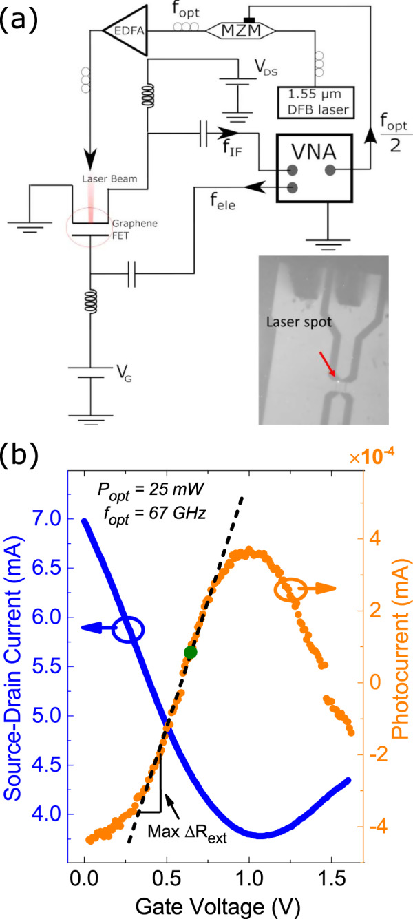
Fig. 2. Measurement setup and device characteristics.

a Experimental setup: a CW laser is modulated via a MZM. It is then amplified with an EDFA and focused on the GFET. An AC signal is applied to the gate. The output fIF is measured on a VNA. Inset: optical image of device with laser focused on the channel. b Blue curve: source-drain current versus gate voltage, for VDS = 200 mV. Orange curve: photocurrent versus gate voltage, generated by a 25 mW beam focused on the SLG channel.
