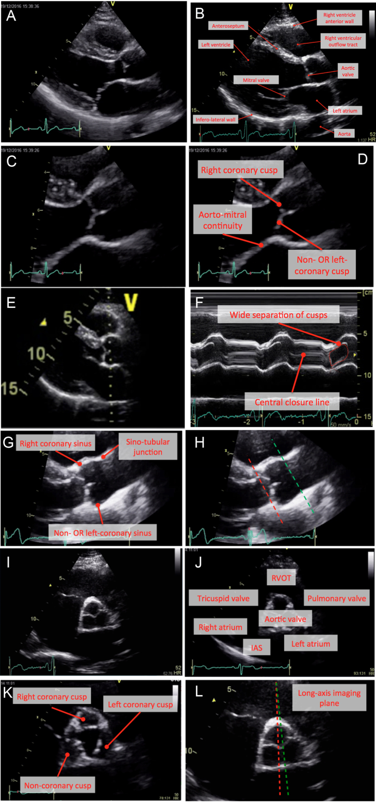
Figure 1.

Normal anatomy. Parasternal long-axis window (A and B), with zoom images (C and D). M-mode recording of the aortic valve should be obtained with the cursor perpendicular to the axis of the aorta (E). Normal M-mode trace (F): note central closure line (labelled). Anatomy of the aorta (G). Image (H) marks the insertion of the cusps (red dotted line) and sino-tubular junction (green dotted line). Parasternal short-axis window at the level of the aortic cusps (images I and J). Image (K) represents a zoomed image of the aortic valve during systole with the three cusps labelled. In image (L), the lines represent potential parasternal long-axis imaging planes. Whilst both transect the right coronary cusp, it is evident that a subtle change in angle of the transducer will lead to the inclusion of either the non-coronary cusp (red dotted line) or left coronary cusps (green dotted line).

 This work is licensed under a